Copyright
©The Author(s) 2019.
World J Gastroenterol. Aug 14, 2019; 25(30): 4051-4060
Published online Aug 14, 2019. doi: 10.3748/wjg.v25.i30.4051
Published online Aug 14, 2019. doi: 10.3748/wjg.v25.i30.4051
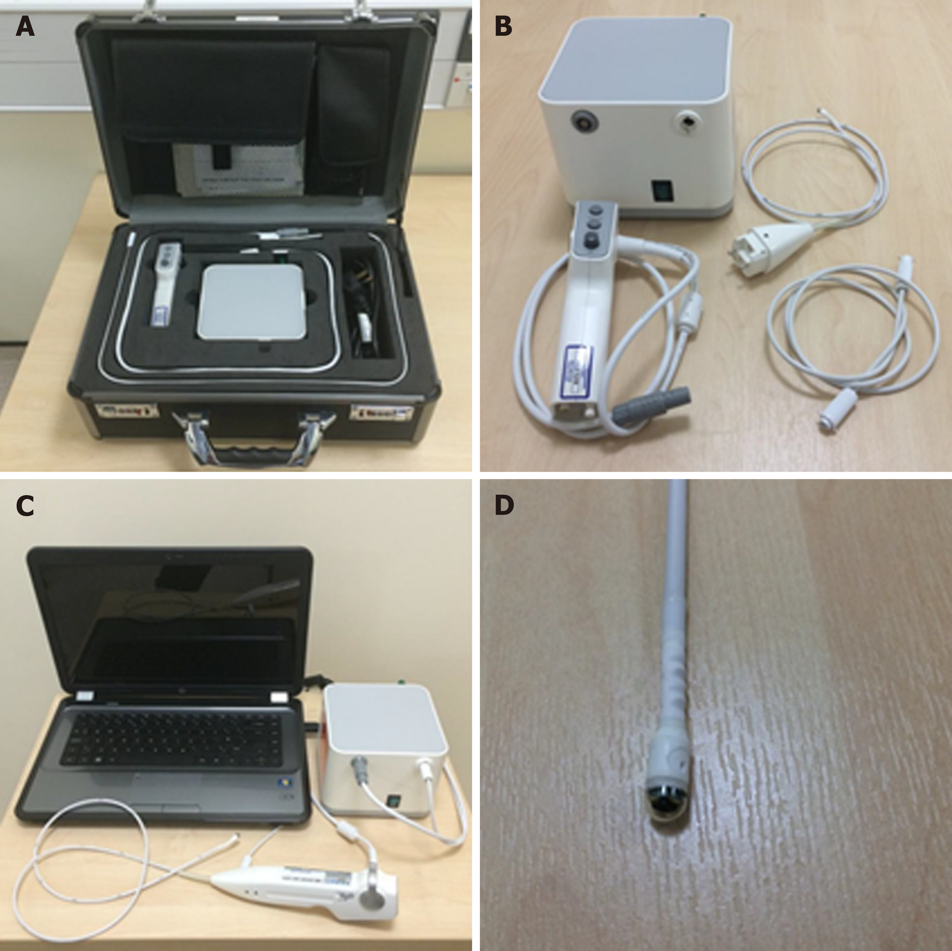
Figure 1 The “EG Scan II” system.
A: The portable case with four main parts; B: The image processor (top left), disposable probe (top right), air tube (bottom right) and hand-held controller (bottom left); C: The system connected and ready for use; D: Close view of the capsule probe tip. Reproduced with permission from Sami SS et al. Copyright John Wiley and Sons.
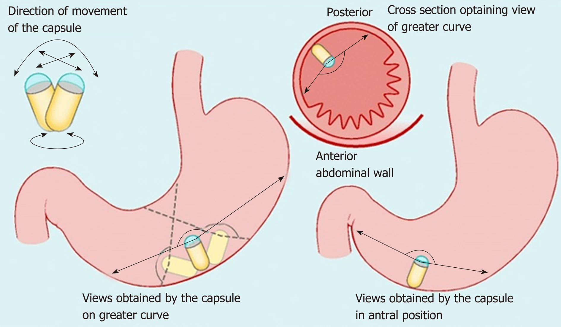
Figure 2 Maneuvers of the magnetically guided wireless capsule endoscopy in the stomach.
Reproduced with permission from Ching HL et al[43]. Copyright Thieme Group.
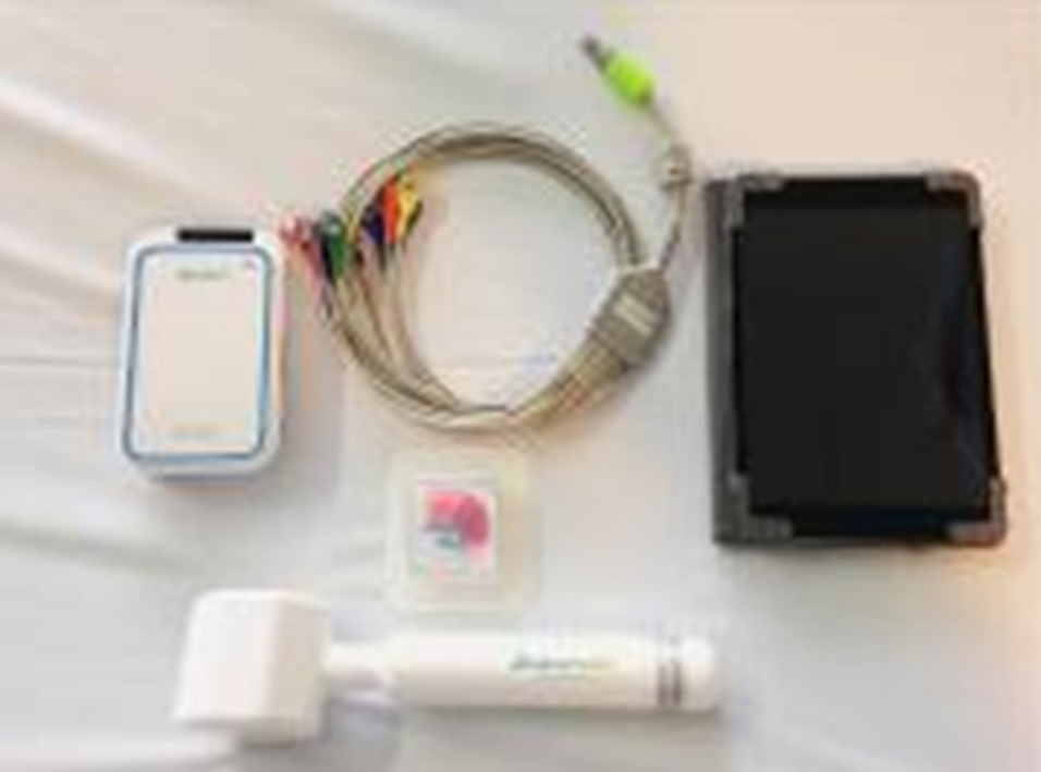
Figure 3 MicroCam Navi equipment (magnetically-assisted capsule endoscopy).
Reproduced with permission from Ching HL et al[38]. Copyright Thieme Group.
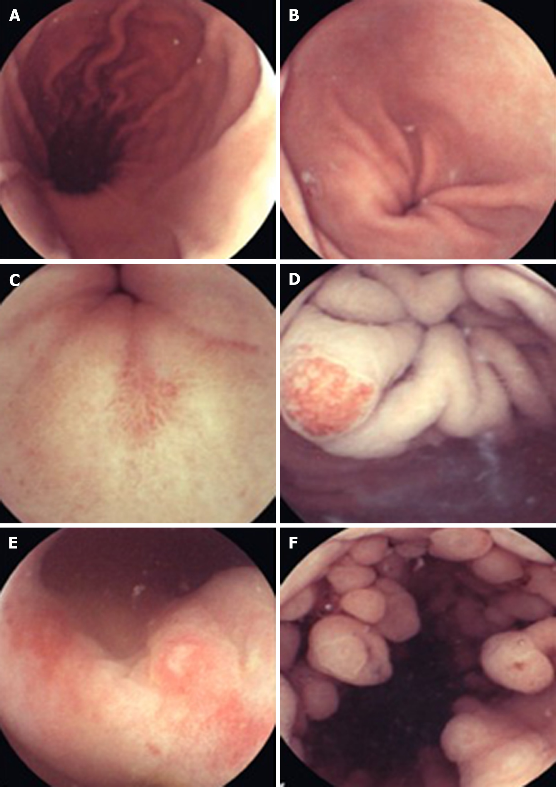
Figure 4 Capsule endoscopy.
A: Longitudinal view of the gastric body and lesser curve. B: Gastric antrum. C: Pre-pyloric erosion. D: Angioectasia in the cardia. E: Nonsteroidal anti-inflammatory drug-related erosive gastropathy. F: Fundic gland polyps. Reproduced with permission from Hale MF et al. Copyright Thieme Group.
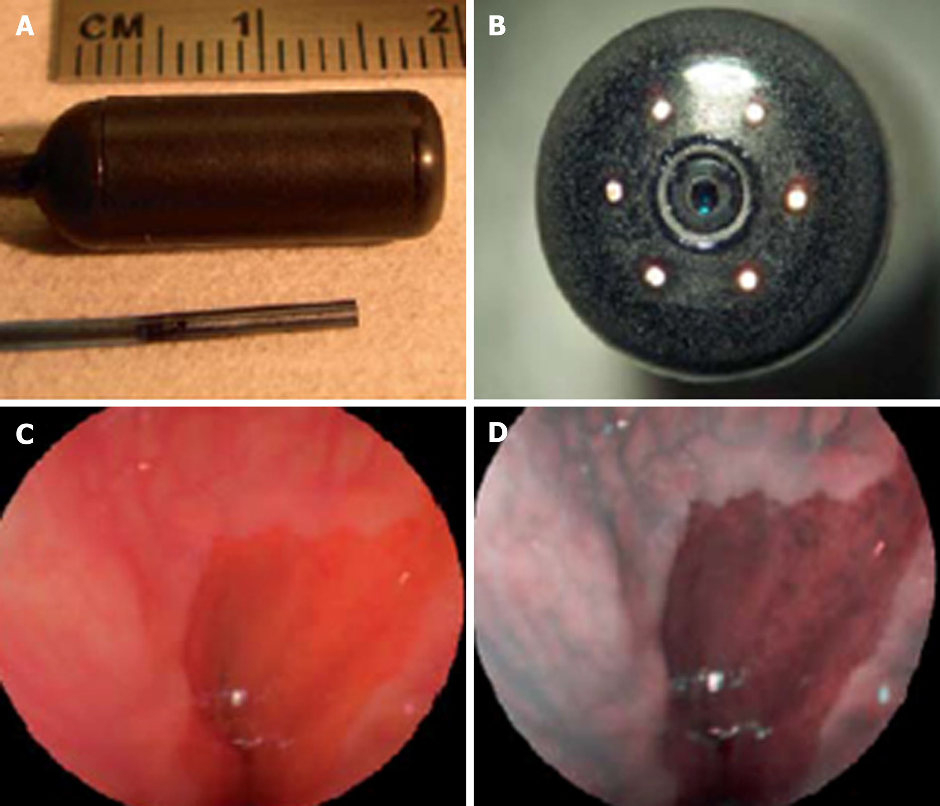
Figure 5 Scanning single fiber endoscopy.
A: Scanning fiber endoscopy (SFE) endoscope probes showing 9 mm rigid tip length of 1.2 mm diameter prototype and 18 mm capsule length of 6.4 mm diameter TCE. A front view of the distal end of the TCE is shown in (B) illustrating that the TCE is a standard SFE probe with collection fibers modified for capsule use. The gastroesophageal junction of a human subject is shown in single 500-line RGB image contrast (C) compared to postprocessed ESI contrast of the same SFE image frame (D). The lighter esophageal tissue is more clearly differentiated from the red-colored gastric mucosa in the ESI image. Reproduced with permission from Lee CM et al[46]. Copyright John Wiley and Sons, Inc.
- Citation: McGoran JJ, McAlindon ME, Iyer PG, Seibel EJ, Haidry R, Lovat LB, Sami SS. Miniature gastrointestinal endoscopy: Now and the future. World J Gastroenterol 2019; 25(30): 4051-4060
- URL: https://www.wjgnet.com/1007-9327/full/v25/i30/4051.htm
- DOI: https://dx.doi.org/10.3748/wjg.v25.i30.4051


