Copyright
©The Author(s) 2022.
World J Clin Cases. Feb 6, 2022; 10(4): 1172-1181
Published online Feb 6, 2022. doi: 10.12998/wjcc.v10.i4.1172
Published online Feb 6, 2022. doi: 10.12998/wjcc.v10.i4.1172
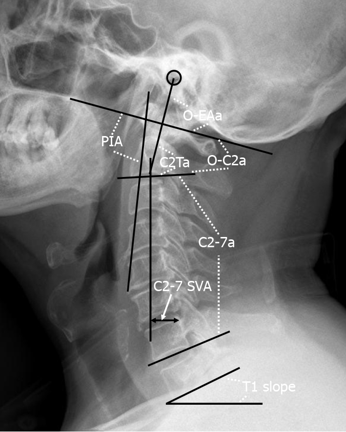
Figure 1 Representation of the radiographic measurements.
O-C2a: The angle between the inferior endplate of C2 and the McGregor line; O-EAa: The angle formed by the McGregor line and the EA-line; C2Ta: The angle formed by the inferior endplate of C2 and the EA-line; C2-7a: The Cobb angle between the lower endplate of C2 and C7; T1 slope: The angle between the horizontal and the T1 superior endplate; C2-7 SVA: The horizontal distance between the C2 plumb line and the posterior corner of C7; PIA: The angle between McGregor line and the line that links the center of the C1 anterior arch and the apex of cervical sagittal curvature. O-C2a: O-C2 angle; O-EAa: Occipital and external acoustic meatus to axis angle; C2Ta: C2 tilting angle; C2-7a: C2-7 angle; SVA: Sagittal vertical axis; PIA: Pharyngeal inlet angle.
- Citation: Zhu C, Wang LN, Chen TY, Mao LL, Yang X, Feng GJ, Liu LM, Song YM. Sequential sagittal alignment changes in the cervical spine after occipitocervical fusion. World J Clin Cases 2022; 10(4): 1172-1181
- URL: https://www.wjgnet.com/2307-8960/full/v10/i4/1172.htm
- DOI: https://dx.doi.org/10.12998/wjcc.v10.i4.1172


