Copyright
©The Author(s) 2020.
World J Clin Cases. Aug 26, 2020; 8(16): 3440-3449
Published online Aug 26, 2020. doi: 10.12998/wjcc.v8.i16.3440
Published online Aug 26, 2020. doi: 10.12998/wjcc.v8.i16.3440
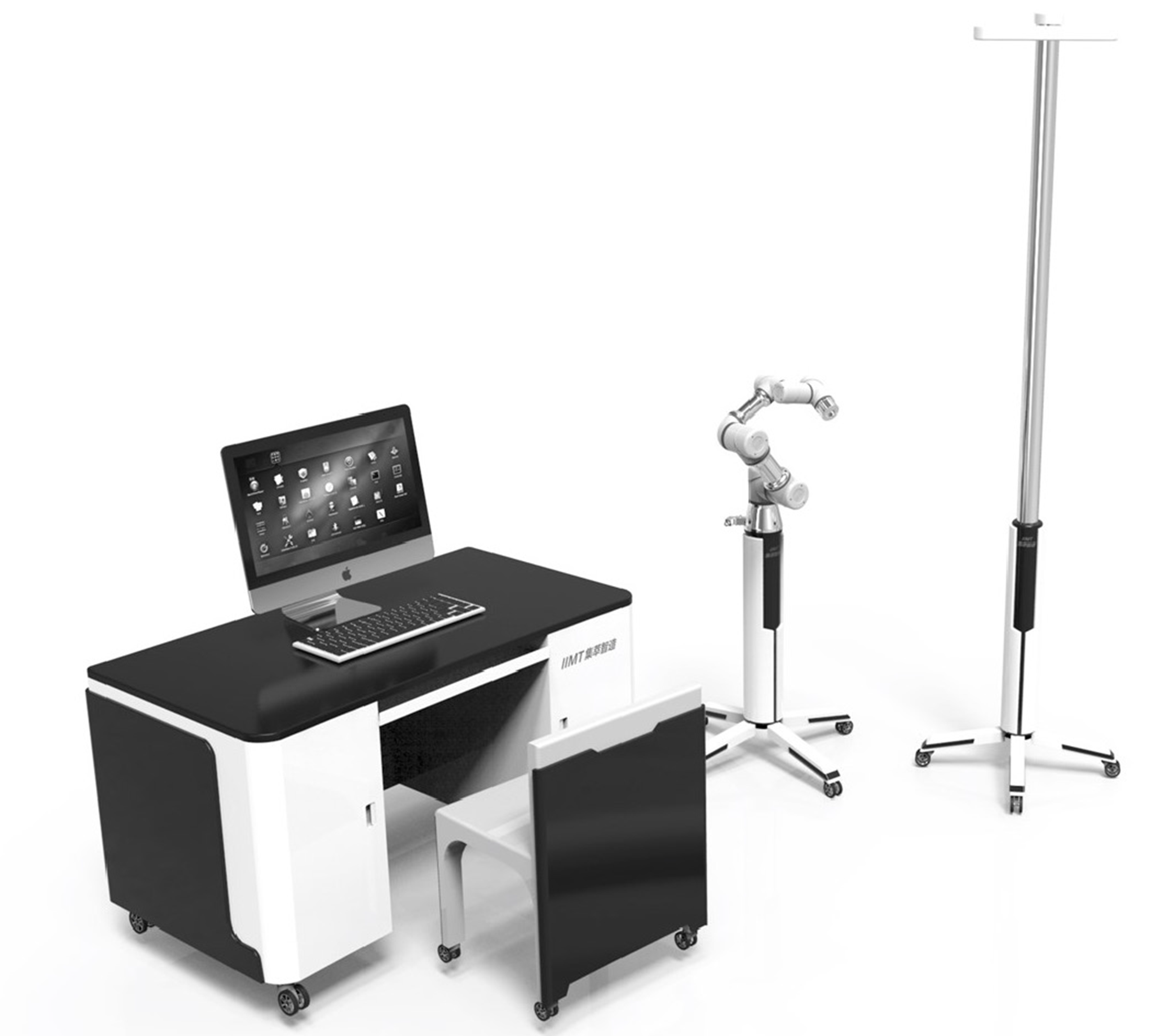
Figure 1 Schematic diagram of the binocular-stereo-vision-based navigation robot.
The navigation robot was composed of binocular stereo visual tracking equipment, an operation planning and controlling system and a six-axis robotic arm.
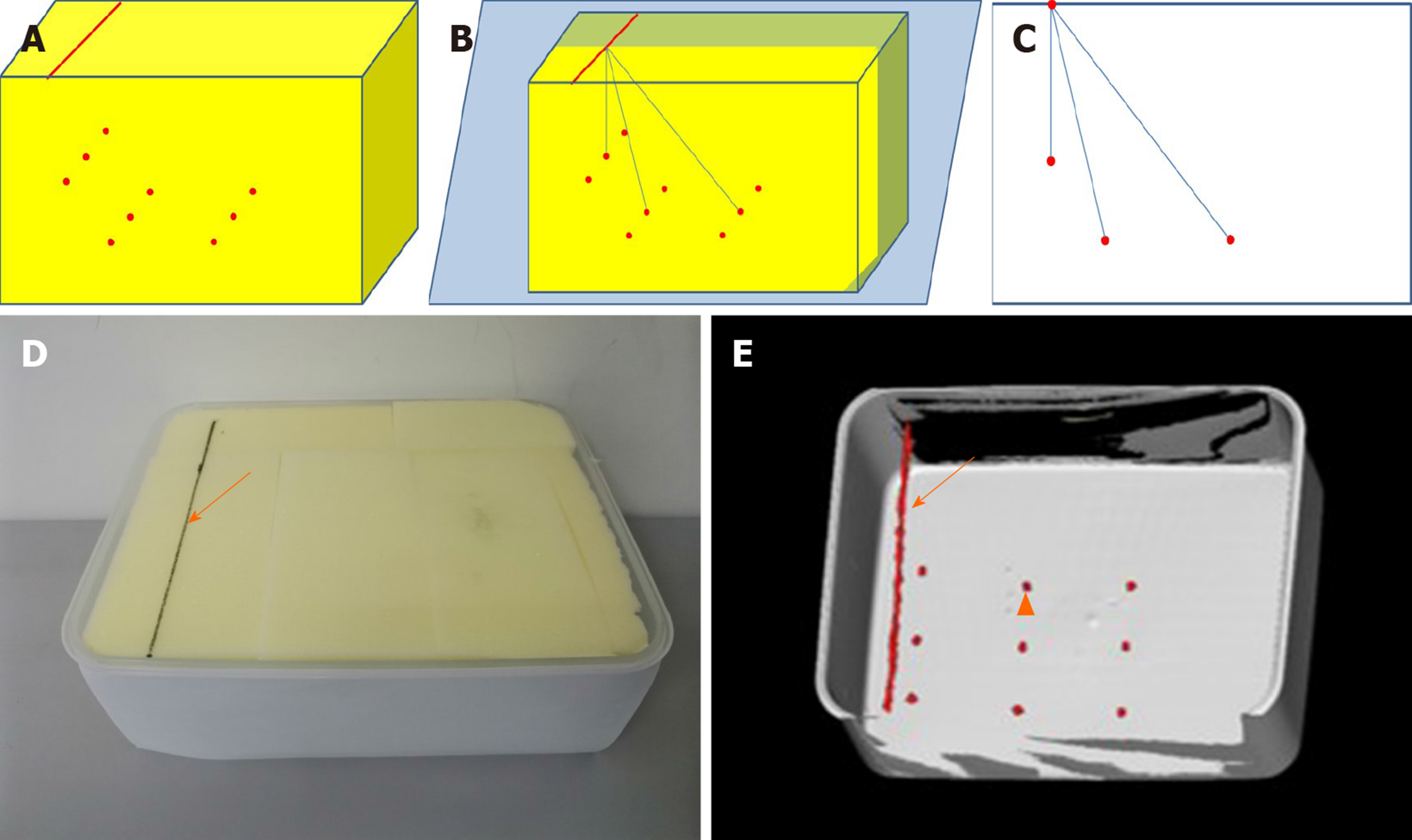
Figure 2 Schematic, photo and three-dimensional computed tomography image of box model.
A: Schematic diagram of box model; B: One insertion line was drawn on the upper surface with contrast agent parallel to the narrow edge; C: Nine artificial targets were set inside the box, respectively 50 mm (target a), 100 mm (target b), 150 mm (target c) far from the insertion line; D: Image and 3D-computed tomography of box model with insertion line and target marked with solid arrow and triangular arrow; E: The box model was made of acrylic resin and filled with sponge.
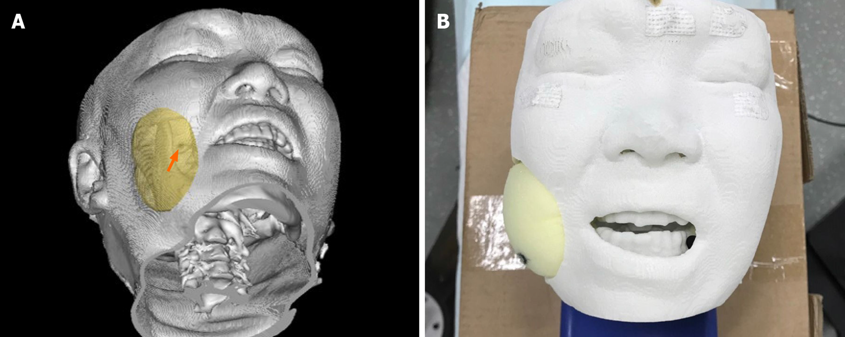
Figure 3 Head phantom.
A: The 1:1 head phantom was 3D printed with nylon and filled with sponge; B: The foramen ovale is marked with solid arrow.
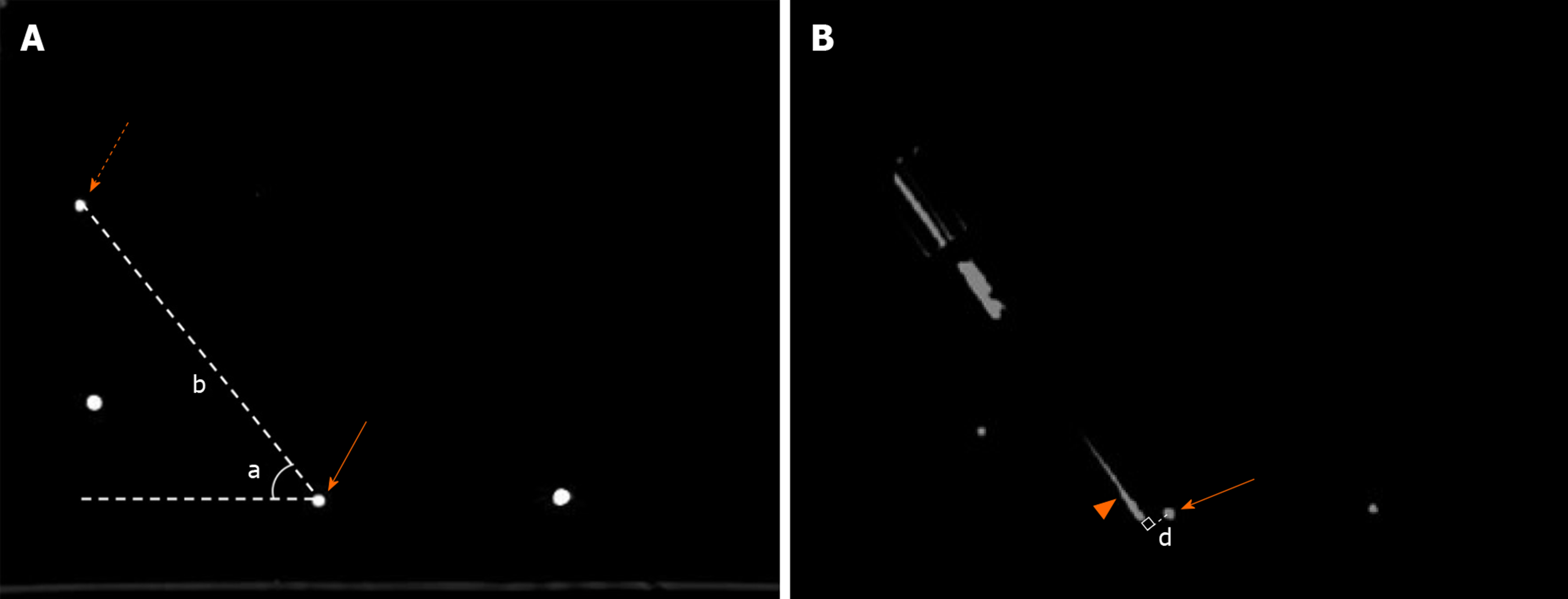
Figure 4 Measurement of insertion parameters and deviation distance.
A: Insertion depth and angle were measured on preoperative planning image. Insertion depth (b) was the distance from entry point (dotted arrow) to target (solid arrow). Insertion angle (a) was the angle of insertion trajectory and horizontal line; B: Euclidian error was the vertical dimension (d) from the center of target (solid arrow) to real needle (triangular arrow).
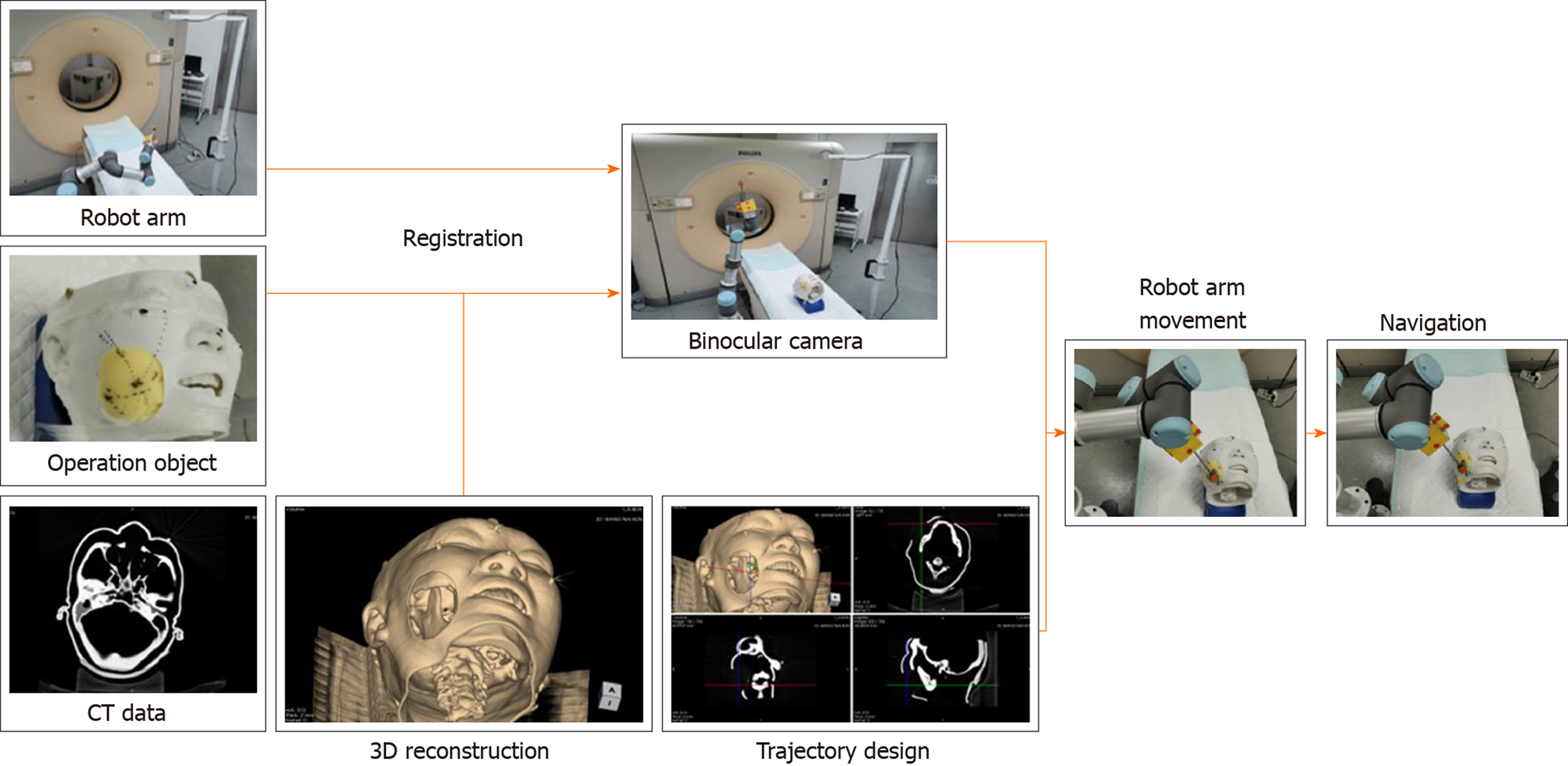
Figure 5 Workflow of robot guided puncture.
Before placement, computed tomography images of operation object with four visual markers on skin were obtained and uploaded to the computer system. The robot arm and stereo camera were placed beside the operation table. After locating the markers on operation object and robot arm with camera, registration process was complicated. Puncture trajectory was designed with the target point and entry point on the insertion line. Then, robot arm was commanded to move to specific position. Needle was inserted through the guiding device at the terminal of robot arm to certain depth.
- Citation: Wang R, Han Y, Luo MZ, Wang NK, Sun WW, Wang SC, Zhang HD, Lu LJ. Accuracy study of a binocular-stereo-vision-based navigation robot for minimally invasive interventional procedures. World J Clin Cases 2020; 8(16): 3440-3449
- URL: https://www.wjgnet.com/2307-8960/full/v8/i16/3440.htm
- DOI: https://dx.doi.org/10.12998/wjcc.v8.i16.3440


