Copyright
©The Author(s) 2024.
World J Orthop. Oct 18, 2024; 15(10): 965-972
Published online Oct 18, 2024. doi: 10.5312/wjo.v15.i10.965
Published online Oct 18, 2024. doi: 10.5312/wjo.v15.i10.965
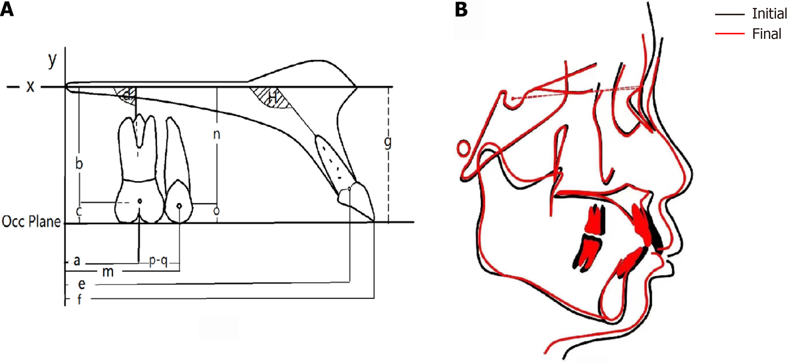
Figure 4 Cephalometric tracings and measurement indicators before and after orthodontic treatment.
A: Tooth movement measurement. The palate plane was set as the X-axis, and the vertical line from the Pt point to the palate plane was taken as the Y-axis. The incisal edge to the U6 mesiobuccal tip was the occlusal plane. a: Distance from the center point of the U6 crown to the Y-axis; b: Distance from the center point of the U6 crown to the X-axis; c: Distance between the center point of the U6 crown and the occlusal plane; d: Angle between the U6 major axis and the X-axis. e: Distance between the U1 reference point and the Y-axis. f: Distance between the U1 incisal edge point and the Y-axis. g: Distance between the U1 incisal edge point and the X-axis. h: Incisor inclination. B: Comparison of pretreatment (black line) and posttreatment (red line) cephalometric tracings.
- Citation: Xie LL, Chu DY, Wu XF. Simple and effective method for treating severe adult skeletal class II malocclusion: A case report. World J Orthop 2024; 15(10): 965-972
- URL: https://www.wjgnet.com/2218-5836/full/v15/i10/965.htm
- DOI: https://dx.doi.org/10.5312/wjo.v15.i10.965


