Copyright
©2014 Baishideng Publishing Group Inc.
World J Radiol. May 28, 2014; 6(5): 139-147
Published online May 28, 2014. doi: 10.4329/wjr.v6.i5.139
Published online May 28, 2014. doi: 10.4329/wjr.v6.i5.139
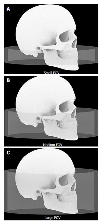
Figure 3 The dimensions of the irradiated regions with different field of view sizes are shown schematically.
A: Small FOV; B: Medium FOV; C: Large FOV. FOV: Field of view.
- Citation: Acar B, Kamburoğlu K. Use of cone beam computed tomography in periodontology. World J Radiol 2014; 6(5): 139-147
- URL: https://www.wjgnet.com/1949-8470/full/v6/i5/139.htm
- DOI: https://dx.doi.org/10.4329/wjr.v6.i5.139


