Copyright
©2011 Baishideng Publishing Group Co.
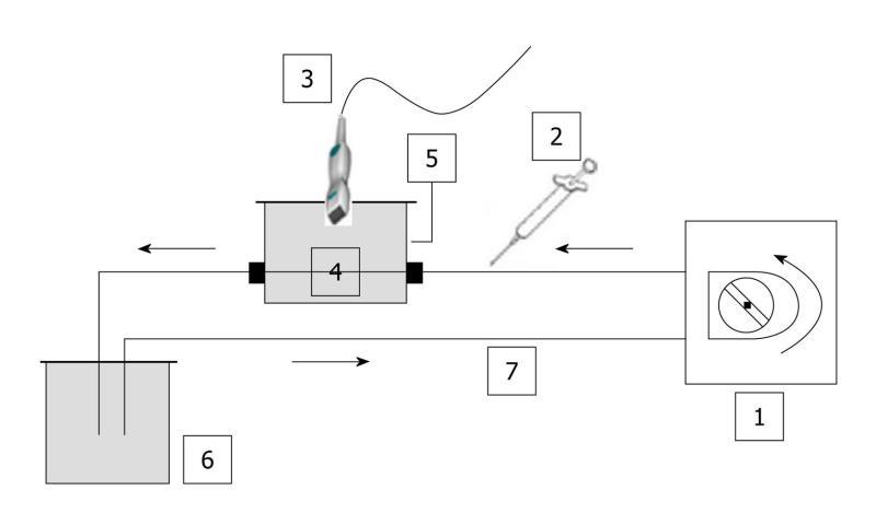
Figure 1 Schematic diagram of the closed-circuit.
No contact with ambient air was possible. In addition, as water was degassed, no significant amount of gas was trapped in the circuit. Based on the same set-up, three phantoms were used throughout the in vitro experiments: (a) a single straight pipe phantom; (b) a three intertwined pipe phantom; (c) a dialyzer. The Gustave Roussy Institute (IGR) ratio was tested throughout the in vitro experiments as it corresponded to the ratio (4.8 mL per patient) previously validated and routinely used at the IGR. 1: Peristaltic pump; 2: Syringe; 3: PZT, PLT 604AT probe; 4: Phantom; 5: Custom-made water tank; 6: Reservoir; 7: Tubing (silicone pipe; internal diameter: 2 mm; wall thickness: 1 mm).
- Citation: Gauthier M, Leguerney I, Thalmensi J, Chebil M, Parisot S, Peronneau P, Roche A, Lassau N. Estimation of intra-operator variability in perfusion parameter measurements using DCE-US. World J Radiol 2011; 3(3): 70-81
- URL: https://www.wjgnet.com/1949-8470/full/v3/i3/70.htm
- DOI: https://dx.doi.org/10.4329/wjr.v3.i3.70


