Copyright
©The Author(s) 2015.
World J Gastrointest Endosc. Jul 10, 2015; 7(8): 777-789
Published online Jul 10, 2015. doi: 10.4253/wjge.v7.i8.777
Published online Jul 10, 2015. doi: 10.4253/wjge.v7.i8.777
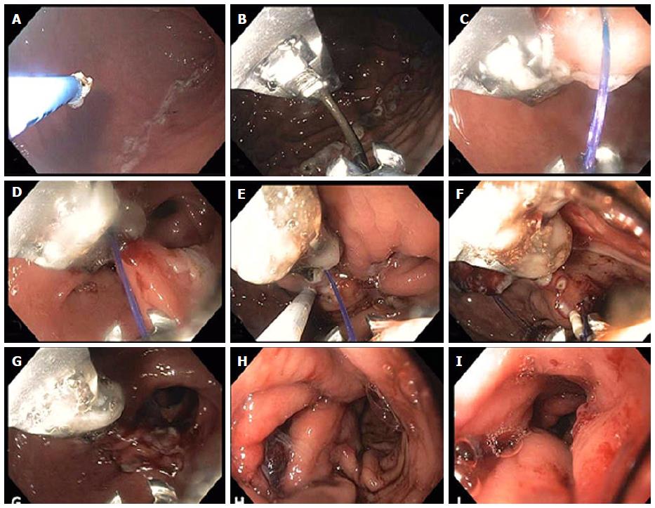
Figure 7 Endoscopic sleeve gastroplasty.
A: Initially argon plasma coagulation is used at a setting of 0.8 L 30 W, forced coagulation to mark the anterior and posterior extents of a corridor that will contain the outer sutures to be placed (as shown in the attached schematic (bites along the anterior wall, greater curvature and posterior wall); B: The suturing device is inserted and placement of the first running outer suture is begun as shown in figures C and D reducing the lumen along the greater curvature of the antrum; E: The helical tissue retractor is used through the second channel of the endoscope as seen in figure E to achieve deep, transmural if possible placement of the sutures and to facilitate suture placement in difficult locations; F: Insertion of the cinch device shown at the 6 o’clock position. The running suture can be seen at 7 o’clock prior to tightening; G: After tightening and cinching of the suture the lumen reduction forming the beginning of the endoscopic sleeve can be seen; H: Completion of the outer sutures showing marked lumen reduction; I: Completion of the inner row of sutures with final appearance of the endoscopic sleeve gastroplasty at the end of the procedure. A tight 3-4 cm tunnel is seen which extends from just distal to the fundus to approximately 3 cm proximal to the pylorus.
- Citation: Stavropoulos SN, Modayil R, Friedel D. Current applications of endoscopic suturing. World J Gastrointest Endosc 2015; 7(8): 777-789
- URL: https://www.wjgnet.com/1948-5190/full/v7/i8/777.htm
- DOI: https://dx.doi.org/10.4253/wjge.v7.i8.777


