Copyright
©The Author(s) 2024.
World J Gastroenterol. Apr 28, 2024; 30(16): 2272-2280
Published online Apr 28, 2024. doi: 10.3748/wjg.v30.i16.2272
Published online Apr 28, 2024. doi: 10.3748/wjg.v30.i16.2272
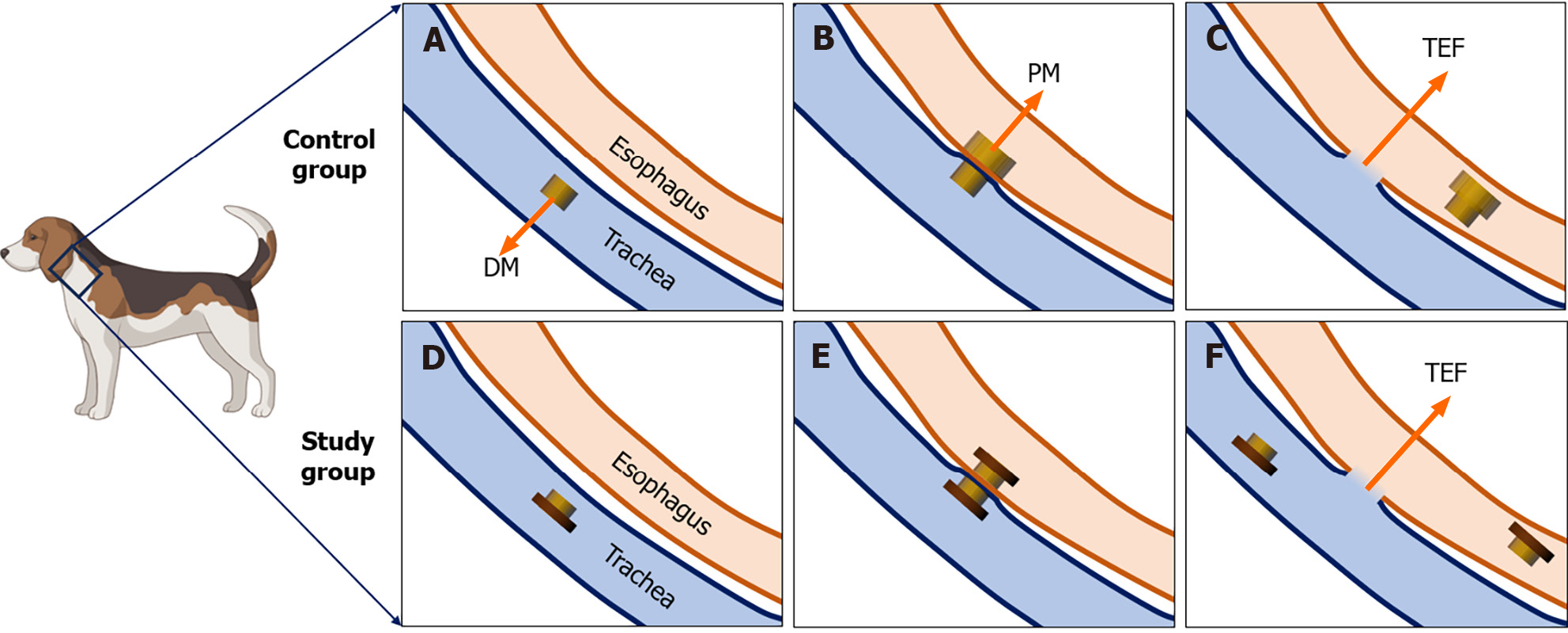
Figure 2 Schematic diagram of the magnetic compression process.
A: The daughter magnet was inserted into the trachea of control dogs; B: The parent magnet was inserted into the esophagus of the control dog where it was then attracted with the daughter magnet; C: The parent magnet and daughter magnet fall off into the distal end of the esophagus, and the tracheoesophageal fistula (TEF) is established in the control group; D: The T-shaped magnet was inserted into the trachea of study dogs; E: Another T-shaped magnet was inserted into the esophagus of the study dog where it attracted with the magnet in the trachea; F: The endotracheal magnet was removed under endoscopy; the endoesophageal magnet entered the distal end of the esophagus; and the TEF was established in the study group. DM: Daughter magnet; PM: Parent magnet; TEF: Tracheoesophageal fistula.
- Citation: Zhang MM, Mao JQ, Shen LX, Shi AH, Lyu X, Ma J, Lyu Y, Yan XP. Optimization of tracheoesophageal fistula model established with T-shaped magnet system based on magnetic compression technique. World J Gastroenterol 2024; 30(16): 2272-2280
- URL: https://www.wjgnet.com/1007-9327/full/v30/i16/2272.htm
- DOI: https://dx.doi.org/10.3748/wjg.v30.i16.2272


