Copyright
©The Author(s) 2016.
World J Gastroenterol. Feb 21, 2016; 22(7): 2326-2335
Published online Feb 21, 2016. doi: 10.3748/wjg.v22.i7.2326
Published online Feb 21, 2016. doi: 10.3748/wjg.v22.i7.2326
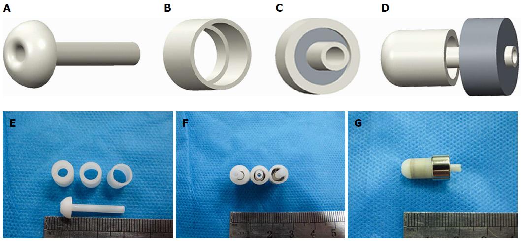
Figure 2 Mode pattern and real pictures of magnet devices.
A: Lateral view of an internal drainage tube; B: View of the biliary part magnet shell; C: Antapical view of the combined biliary part; D: Lateral view of biliary part approach to enteric part; E: The internal drainage tube and shells of different crimping areas; F: Magnets with different pressures; G: Biliary part and enteric part coupled together.
- Citation: Xue F, Guo HC, Li JP, Lu JW, Wang HH, Ma F, Liu YX, Lv Y. Choledochojejunostomy with an innovative magnetic compressive anastomosis: How to determine optimal pressure? World J Gastroenterol 2016; 22(7): 2326-2335
- URL: https://www.wjgnet.com/1007-9327/full/v22/i7/2326.htm
- DOI: https://dx.doi.org/10.3748/wjg.v22.i7.2326


