Copyright
©2009 The WJG Press and Baishideng.
World J Gastroenterol. Jan 21, 2009; 15(3): 289-299
Published online Jan 21, 2009. doi: 10.3748/wjg.15.289
Published online Jan 21, 2009. doi: 10.3748/wjg.15.289
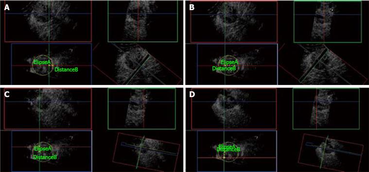
Figure 11 3D CE-US.
A: Ellipse marks the tumor border at its maximal diameter (5 cm). First needle electrode insertion is planned from the elevation plane (Blue box) at 1 cm from the edge of the tumor. Green and Red orthogonal planes mark the trajectory of the needle electrode. B: Distance B measures 2.5 cm from the first needle electrode insertion and plans the plane (Green) of insertion for the next two needle electrodes. C: The second needle electrode is placed at the Green and Red planes intersection measuring 1.5 cm superior to the last position. D: Third needle insertion is placed at the Red and Green plane intersection, 3 cm below the second needle electrode as shown on the Blue plane.
- Citation: Leen E, Kumar S, Khan SA, Low G, Ong KO, Tait P, Averkiou M. Contrast-enhanced 3D ultrasound in the radiofrequency ablation of liver tumors. World J Gastroenterol 2009; 15(3): 289-299
- URL: https://www.wjgnet.com/1007-9327/full/v15/i3/289.htm
- DOI: https://dx.doi.org/10.3748/wjg.15.289


